  |   |   |
|
| USB powered with ESD / overvoltage / transient circuit protection | |||
| CAN2.0A and B and CANFD bus compatibility (ISO11898-1) | |||
| Max speed per channel: – CAN 2.0 – 1000 kbit/s – CAN FD Bit Rate Switch Multiplier (x10) – 10000 kbit/s | |||
| Support for CAN-bus silent/listen-only mode | |||
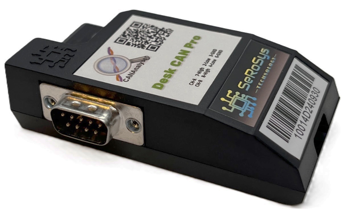
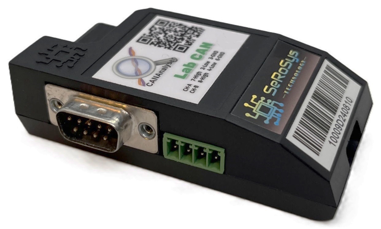
| Dual male + female passthrough DB9 pinout compatible with CiA® 106 for CAN channel A | |||
| 1 microsecond timestamp resolution | |||
| Ring log recording buffer of 1,000,000 messages | |||
| Data view format in Hex, Decimal and Binary, plus ASCII in parallel | |||
| Software language support in English and German | |||
| LEDs provide visual indication of power, connection, bus traffic, mode | |||
| Temperature range: -40 C to +85 C | |||
| IP40 plastic enclosure rating | |||
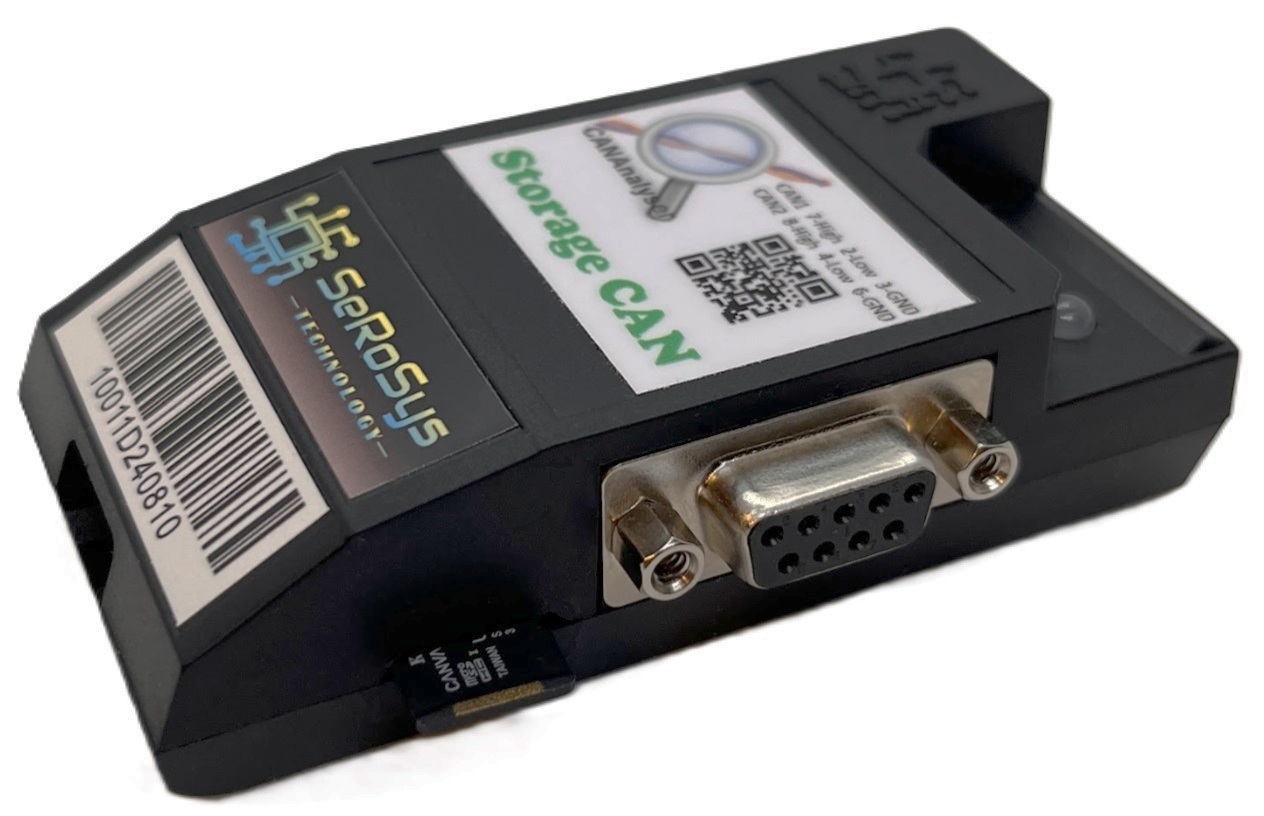
| Micro-SD card slot for datalogging | |||
| Power over D-SUB connectors in addition to USB powered | |||
| D-SUB power voltage supply range: +7 V to +28 VDC (nominal ~= 12 VDC) | |||
| D-SUB power electrically protected against over-voltage, reverse battery, ESD, transients | |||
| GPIO uses automotive grade I/O | |||
| 2 Input and 2 input GPIO pins | |||
| GPIO regulator enables thermal circuit protection at over-temp and disables power | |||
| Short Circuit Protection on all GPIO pins | |||
| GPIO inputs protected from -43VDC to 45VDC | |||
| GPIO outputs provide up to 100mA steady state at CMOS logic levels (0V / 5V) | |||
| GPIO outputs support input overvoltage protection to 28VDC | |||
| Price | |||
| Datasheet | Coming Soon | Coming Soon |
Shopping Cart